User Setup Guide
Thank you again for choosing our products. This guide will help you set up the AnyShake Explorer in a few simple steps—typically in less than one hour.
If you have any questions during the setup, feel free to reach out for technical support. Read our technical support policy for more details.
Before Setup
Make sure you have the following items ready:
- AnyShake Explorer Kit
- This guide assumes the Full Kit version
- Power Adapter
- Voltage range: 9 V–12 V DC (recommended: 12 V)
- Polarity: Inner pin is positive (+), outer barrel is negative (−). This can be confirmed by checking the polarity symbols on the power adapter.

- Data Cable (choose one):
- (preferred) RS-232 cable with DB9 connector, if the target computer does not have an RS-232 port, you can use an RS-232 to USB cable.

- RS-485 cable with 2-pin terminal block, if the target computer does not have an RS-485 port, you can use an RS-485 to USB cable.
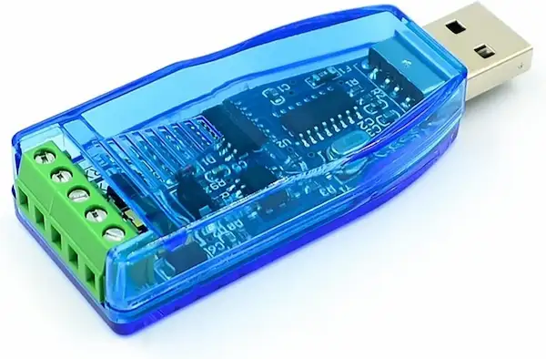
- (preferred) RS-232 cable with DB9 connector, if the target computer does not have an RS-232 port, you can use an RS-232 to USB cable.
- Active GNSS Antenna (optional for GNSS sync)
- 3.3 V bias voltage
- L1/L5 dual-frequency recommended (GPS / Galileo / QZSS compatible)
- Make sure the antenna has SMA connector (male)

Setup Procedure
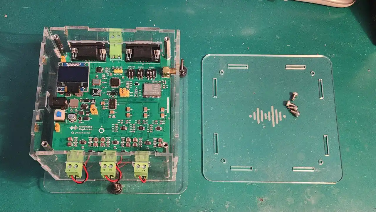
1. Disassemble the Top Acrylic Panel
Use the included Allen screwdriver to remove the top acrylic panel. This allows you to configure the operating mode.
Refer to Mode Configuration and Display for details on DIP switch settings.
For example, to set:
- Sample Rate: 100 SPS
- Baud Rate: 115200
- GNSS mode: Enabled
- 6-Channel mode: Enabled
Set the DIP switches as follows:
-
SW3: Sample Rate
Bit State 1 ON 2 OFF -
SW5: Baud Rate
Bit State 1 OFF 2 ON -
SW6: Operating Mode
Bit Description State 1 Accelerometer-only OFF 2 GNSS Enable ON 3 6-Channel Mode ON
2. Choose an Installation Site
Place the device on a flat, rigid, and stable surface, ideally directly coupled to a concrete slab or foundation. This ensures good mechanical coupling to the ground, which is essential for accurate low-noise seismic measurements. Recommended locations include:
- Basement concrete floors
- Garage or utility room slab
- Reinforced indoor foundations
- Ground-level concrete surfaces
Avoid placing the unit on wood floors, tables, or platforms that may introduce micro-vibrations or resonance, also avoid the following:
- Locations near sources of vibration (e.g., HVAC systems, refrigerators, pumps, motors).
- Areas with electromagnetic interference (e.g., Wi-Fi routers, switching power supplies, SBCs like Raspberry Pi if placed too close).
- Surfaces that are unstable or that may shift over time.
Orientation
The geophones inside AnyShake Explorer are aligned along the standard seismic axes:
- Vertical (Z)
- East-West (E)
- North-South (N)
Precise alignment is not required for general use, but it improves consistency when comparing across multiple devices or with regional seismic networks.
To ensure proper orientation and accurate data, please align the device so that the north arrow (N) printed on the PCB (as shown below) is pointing toward true north. This directional indicator is located next to the AnyShake Explorer logo on the PCB silkscreen.
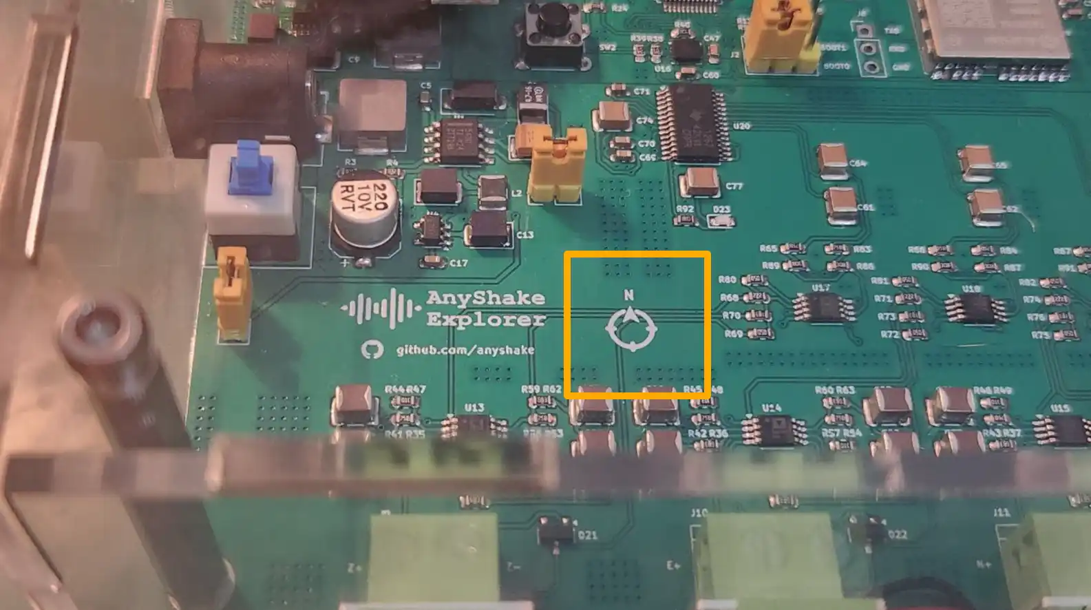
Use a compass (or a smartphone compass App) to determine the correct direction.
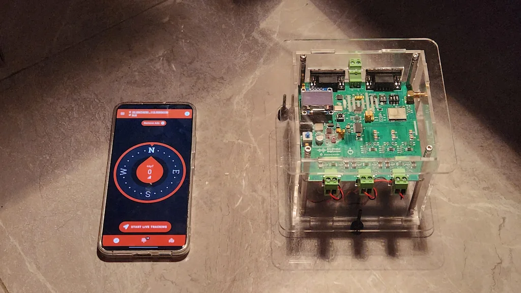
The geophones contain permanent magnets, which will interfere the results if the compass is held too close to the device. To avoid magnetic interference:
- Hold the phone at least 20–30 cm away from the device when using the compass.
- Cross-check the direction using a mechanical compass if available.
GNSS Antenna
If you enabled the GNSS mode, follow these guidelines:
- Place the GNSS antenna near a window or outside wall with a clear view of the sky.
- Avoid placing the antenna under metal roofs or next to tall buildings or walls.
- If possible, install the antenna outdoors using a weatherproof SMA extension cable (≤5 m preferred).
- Use UV- and water-resistant tape or sealant to secure and protect the cable.
Cable Routing
- Route the power and data cables away from AC mains wiring, fluorescent lamps, or other high-frequency noise sources.
- Try to avoid sharp bends or strain on the RS-232 / RS-485 / GNSS cables.
- Ensure that all connectors are fully seated and secured before powering on.
For the most accurate results, leave the device undisturbed after installation. Even small movements (e.g., footsteps nearby) can show up in the seismic signal.
3. Connect the Power and Cables
- Connect the DC power adapter to the power jack.
- Plug in the RS-232 or RS-485 cable to the appropriate port.
- Connect the GNSS antenna to the SMA port if you are using GNSS.
Be careful not to reverse the polarity of the power supply. Always use the included or certified adapter.
4. Switch to Leveling Mode and Power on
To help with alignment, toggle the BOOT and OPTIONS jumper to leveling mode (BOOT0=0, BOOT1=1, OPTIONS=000). This mode activates the onboard accelerometer to measure tilt in real time.
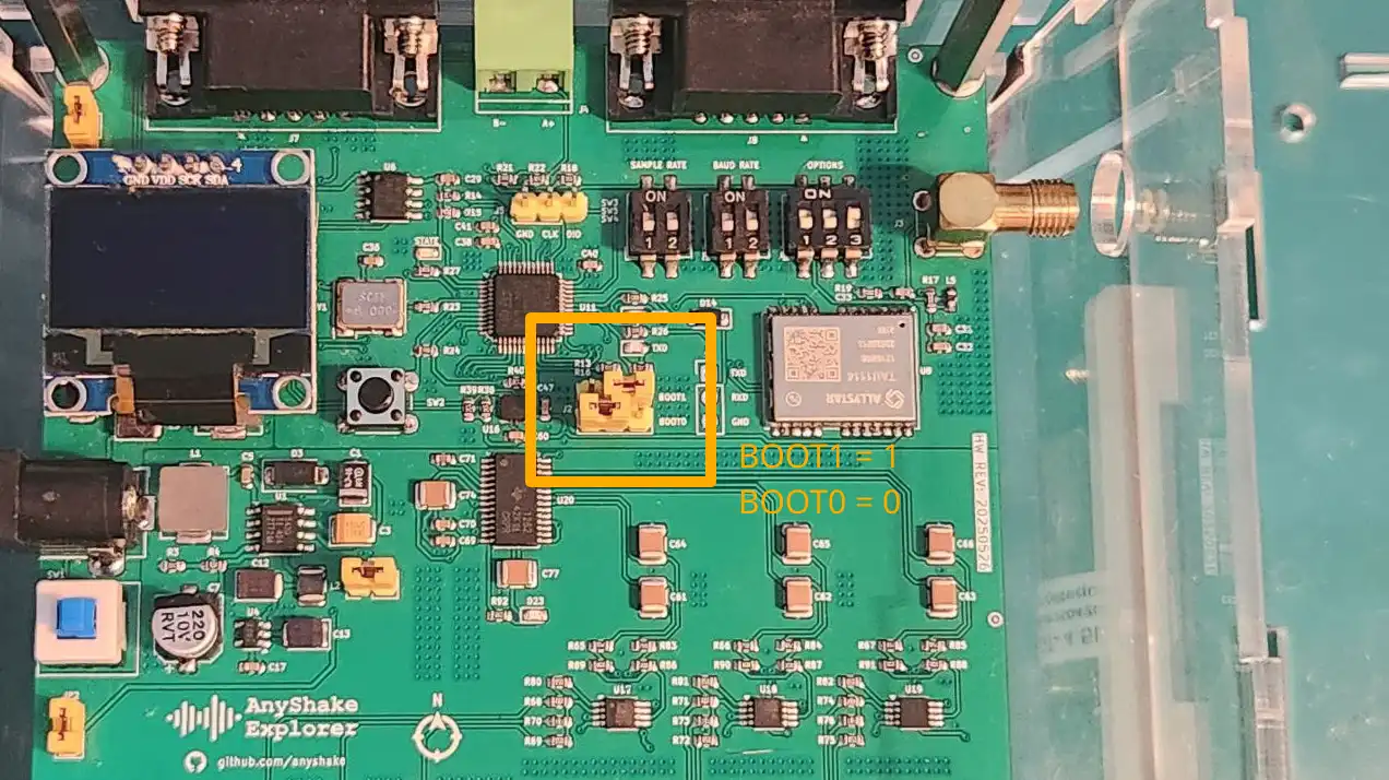
Power on the device using the self-locking power switch. After a few seconds, the device will start to collect tilt data and display it on the OLED screen.
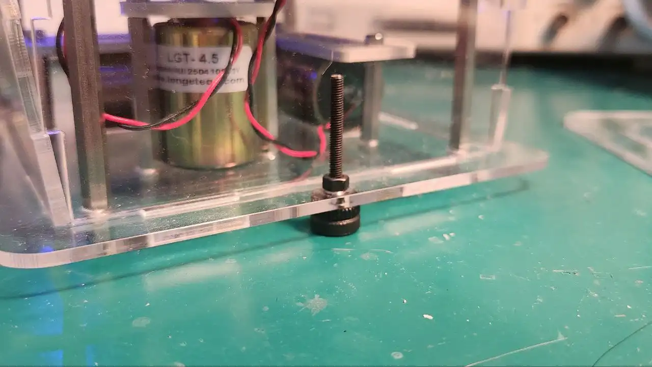
5. Level the Device Using Adjustable Screws
AnyShake Explorer is equipped with three leveling screws located on the bottom of the device. These allow for precise mechanical leveling to ensure accurate orientation of the geophones. Follow these steps to level the device:
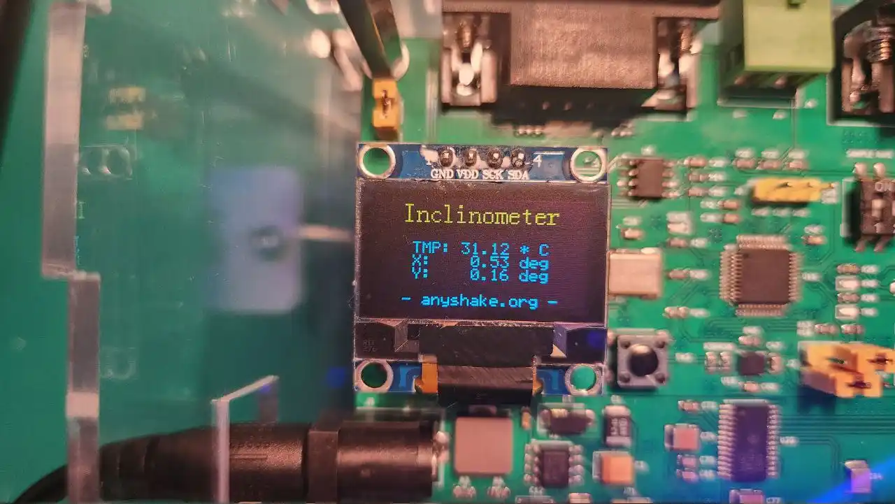
- Observe the inclination values (X and Y axes) displayed on the OLED screen.
- Carefully adjust the three leveling screws to bring both axes as close to zero as possible.
- A recommended tolerance is within ±0.1°.
- Adjust screws gradually and evenly to avoid stress on the acrylic frame.
Once the device is level, press the power button again to turn it off.
6. Switch to Data Acquisition Mode and Restart
Now that leveling is complete, configure the device to start collecting seismic data:
- Set the BOOT mode jumper to data acquisition mode:
BOOT0 = 0,BOOT1 = 0
- Press the power button again to restart the device.
If GNSS mode is enabled:
- The device will wait until a valid GNSS fix is acquired.
- Acquisition starts only when:
- Number of visible satellites > 0
- Horizontal Dilution of Precision (HDOP) ≤ 1.0
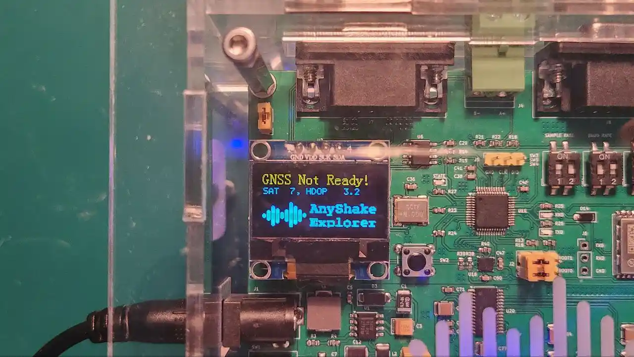
Once synchronization is successful, the device will enter data acquisition mode, and device status and connection information will be displayed on the OLED screen.

After Setup
Once your device has entered data acquisition mode:
- Connect to your host system (e.g., PC, home server, Raspberry Pi, or NUC) using the serial cable you selected during setup.
- Follow the documentation to deploy and launch AnyShake Observer, the official companion software for real-time monitoring and analysis.
- Use the Observer interface to visualize waveforms, configure services, review historical data, and much more.
You're now ready — happy exploring!