What Seismograph Manufacturers Won’t Tell You - A Practical Guide to Efficient Teleseismic Monitoring on a Limited Budget
Introduction
Teleseismic signals refer to seismic waves generated by earthquakes occurring hundreds to thousands of kilometers away. Monitoring these signals provides valuable geophysical information—such as Earth’s internal structure and event characteristics—and is therefore useful for scientific research, education, and hobbyist networks.
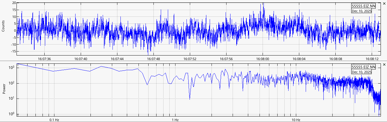
Compared with local earthquakes, teleseismic waves exhibit much lower frequencies, typically below 2 Hz (Fig. 1), and significantly smaller amplitudes. For example, when an earthquake from Alaska arrives in the Philippines, its dominant frequency content often lies in the 1/f noise–dominated band, making the useful signal easily masked and the seismic phases difficult to detect reliably.
On the other hand, traditional seismic instruments such as force-balance accelerometers (FBA) and very-broadband (VBB) seismometers offer excellent low-frequency response and high SNR, but their cost is prohibitive for individuals, schools, or small research groups.

With the rise of low-cost sensors, open-source hardware, and inexpensive microcontrollers, low-cost teleseismic monitoring has become feasible. This application note discusses how to implement a teleseismic monitoring system under budget constraints, including sensor selection, data acquisition architecture, cost-performance trade-offs, and deployment considerations.
Sensor Selection
In a teleseismic monitoring system, the sensor is the core component that determines overall data quality and usability. A capable teleseismic sensor must satisfy requirements in frequency response, noise performance, dynamic range, and long-term stability.
ADI’s documentation on seismic monitoring and structural sensing highlights that modern seismic systems must achieve a balanced compromise between cost and performance, and must adopt sensing technology appropriate to the intended application.
This section compares the commonly used sensor types—MEMS accelerometers and geophones—and provides technical recommendations specifically for teleseismic monitoring.
MEMS Accelerometers
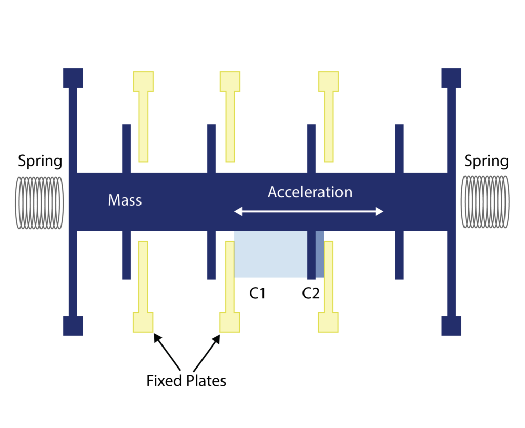
MEMS accelerometers use microfabricated mechanical structures to convert ground motion into electrical signals. They are widely used in portable acceleration sensing and structural vibration monitoring. A typical device consists of a silicon proof mass suspended by thin flexures, forming differential capacitors with fixed electrodes. Motion of the mass changes capacitance, which is then converted into a voltage proportional to acceleration (Fig. 2).
The main advantages of MEMS accelerometers include compact size, low power consumption, and seamless integration with low-cost microcontrollers and SoCs.
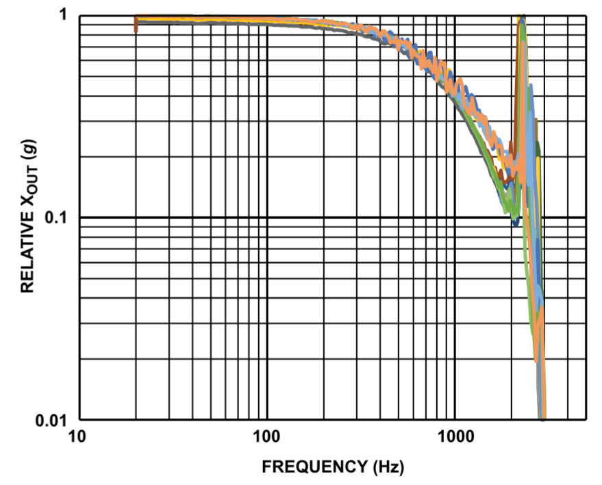
The frequency response of most MEMS accelerometers resembles a low-pass filter with a cutoff at the mechanical resonance frequency. Because of offset drift, MEMS devices typically perform better at frequencies relatively close to—but below—the resonance, and degrade rapidly toward the extremely low-frequency band (Fig. 3).
At low frequencies, MEMS accelerometers exhibit significant 1/f noise (flicker noise), originating from mechanical friction, charge trapping, and low-frequency drift in the internal amplifier. As frequency decreases, noise density increases. Even in the absence of motion, random low-frequency fluctuations can appear comparable to real teleseismic amplitudes (Fig. 4).
Low-frequency MEMS output is further affected by:
- Sensor bias drift: Long-term baseline drift behaves like 1/f noise and reduces weak-signal detectability.
- Temperature-induced offset drift: Temperature variation causes baseline shifts over time, often exceeding the amplitude of teleseismic signals.
Combined 1/f noise, offset drift, and temperature effects severely limit MEMS SNR in the teleseismic band (< 2 Hz). Weak P, S, and surface waves may be obscured. Even with software filtering, numerical integration, or temperature compensation, accurate velocity or displacement reconstruction remains difficult.
To address these issues, manufacturers such as EPSON introduced ultra-low-noise quartz-resonant MEMS accelerometers (link). Although significantly more stable, they cost hundreds of times more than standard low-noise MEMS devices. Thus, while MEMS accelerometers perform well in low-cost structural monitoring or local earthquake detection, they are not suitable as primary sensors for high-quality teleseismic monitoring.
Geophones
Geophones are velocity sensors that use a mass-spring and coil-magnet structure to convert ground motion into electrical signals. They output velocity directly, eliminating the need for integration in seismic phase analysis.
Based on internal topology, geophones come in moving-coil and moving-magnet types (Fig. 5):

They work similarly; the difference lies in which component moves:
- Moving-coil: The housing and permanent magnet remain fixed, while the coil—mounted to the suspended mass—moves.
- Moving-magnet: The housing and coil assembly remain fixed, while the permanent magnet is attached to the suspended mass.
Although their operating principles are almost identical and overall performance is comparable, moving-coil designs are easier to manufacture and therefore more widely used in seismic exploration and teleseismic monitoring.
The transfer function of a geophone can be expressed as:

Where:
- K₀ — Open-loop sensitivity (V/m/s)
- ω₀ — Natural angular frequency (rad/s), with ω₀ = 2πf₀
- f₀ — Resonant frequency
- ξ₀ — Damping ratio
Assuming a geophone with parameters:
- f₀ = 4.5 Hz
- K₀ = 100 V/m/s
- ξ₀ = 0.65
The simulated frequency response is shown in Fig. 6.
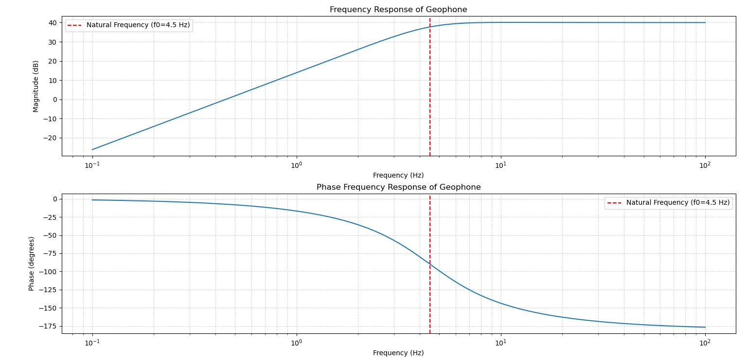
As illustrated, above the resonant frequency the velocity response is approximately flat, whereas below resonance the output rolls off rapidly.
For most low-cost applications, 4.5 Hz geophones are the best choice (Fig. 7). Lower-frequency geophones (e.g., 2 Hz) cost ~10× more, while higher-frequency ones (e.g., 10 Hz) have poor low-frequency response and are unsuitable for teleseismic monitoring.
To extend the bandwidth and improve low-frequency response, external compensation networks are commonly applied to reshape the geophone transfer function. Several approaches exist:
-
Passive servo compensation: This method uses an RC network placed in parallel with the geophone output to increase the effective mass of the moving system and thereby lower the resonant frequency (Fig. 8). However:
- The resulting damping ratio becomes greater than 1, deviating from the optimal value (≈0.707).
- Sensitivity decreases significantly.
- Large capacitors often exhibit poor temperature stability, degrading overall performance.
-
Feedback compensation: A controlled current is injected into the geophone coil. This current generates a corrective force on the suspended mass. A positive-feedback filter—typically integrative—derives this current from the geophone output (Fig. 9). This effectively amplifies low-frequency mass motion, extending bandwidth. However:
- Designing a stable positive-feedback loop is difficult.
- Phase margin and loop stability must be strictly maintained.
-
Pole-zero compensation (recommended): Pole-zero compensation inserts a correction network in series with the geophone so that the zeros of the correction network cancel the poles of the original sensor. The modified system’s poles then become those of the external network (Fig. 10).
Advantages:
- Does not modify the geophone’s internal mechanical characteristics
- Provides controlled and predictable frequency shaping
- Can be implemented in analog circuitry or digital filters
- Lowest cost among practical compensation methods
This approach is widely regarded as the most effective technique for low-cost seismic instrumentation.

Data Acquisition Scheme
Data acquisition is critical in teleseismic monitoring. The objective is to convert the geophone’s millivolt-level analog signal into a digital stream without distortion, without adding significant noise, and with precise timing for phase alignment across sensors.
Three major components:
- Signal preprocessing
- ADC conversion
- Data handling and transmission
Input Voltage Clamping
Clamping limits input voltage to the ADC’s safe range. For example, with ±10 V ADC range, a clamp prevents over-range events using diode-based structures (Fig. 11).

Pre-Amplification
Low-noise op-amps amplify the velocity signal to match ADC dynamic range. Zero-drift amplifiers such as ADA4522 or ADA4528 (Fig. 12) provide microvolt-level offsets and extremely low drift and 1/f noise—ideal for low-frequency, weak signals.
In low-cost designs, external amplifiers may be omitted and replaced with internal ADC PGA—but internal PGAs have higher noise and limited input impedance.
Anti-Aliasing Filter
An anti-aliasing filter is used to suppress frequency components above the Nyquist frequency before the signal enters the ADC. Without proper filtering, high-frequency noise will fold back into the passband during sampling, resulting in irreversible contamination of the recorded data (see Fig. 13).

A well-designed anti-aliasing filter is a critical part of the analog front-end, as it directly determines whether the ADC receives a clean signal and, consequently, whether the system can reliably detect low-frequency teleseismic events.
Fundamentally, the anti-aliasing filter is an analog low-pass filter, which may be implemented using passive or active circuitry. Digital filtering cannot substitute for it, since digital filtering occurs after sampling and therefore cannot prevent aliasing.
In practical designs, the cutoff frequency is typically chosen slightly below half the sampling frequency to ensure adequate roll-off. The quality of this filter is one of the most decisive factors affecting the ADC input integrity and the system’s ability to resolve teleseismic signals in the low-frequency band.
Analog-to-Digital Converter (ADC)
The ADC converts the extremely weak analog signal from the geophone into digital samples. As the most critical and cost-intensive component in the acquisition chain, ADC selection must balance performance, stability, and supply availability.
For seismic monitoring applications, the essential ADC specifications include:
- Resolution: Determines the smallest detectable change in signal. Seismic instruments typically use 24-bit converters.
- Effective Number of Bits (ENOB): More meaningful than nominal resolution; reflects real-world accuracy.
- Dynamic Range: Indicates the ability to measure very weak and very strong signals simultaneously.
- Input-referred Noise: The most important metric for seismic monitoring; sets the minimum detectable signal.
- Sampling Rate: Teleseismic monitoring generally requires 50–200 SPS; the ADC must support stable operation at these rates.
- Input Front-End Architecture: Differential inputs, internal PGA structure, reference voltage design, etc.
- Temperature Drift & Long-Term Stability: Critical for continuous long-term recording.
- Product Lifecycle (EoL status): Avoid devices at or near end of life.
Delta-Sigma (Δ-Σ) ADCs are ideal for seismic- and audio-band applications due to:
- Very high resolutions (commonly 24-bit)
- High oversampling ratios
- Extremely low input noise
- Wide dynamic ranges
Their weakness is limited bandwidth, making them unsuitable for high-speed sampling. Typical examples include:
- ADS1256
- ADS127L01
- AD7768 series
- LTC2500 series
SAR (Successive Approximation) ADCs are better suited for high-speed applications. However, for low-frequency micro-signal measurement, SAR noise and dynamic range are generally inferior to Δ-Σ converters. SAR devices may still be used for high-frequency seismic or SHM applications. Common examples include MCP3208 and LTC1867.
For low-cost seismic applications, a suitable Δ-Σ ADC should meet:
- Input noise < 500 nV/√Hz (0.1–10 Hz band)
- 24-bit resolution or higher
- True delta-sigma architecture
Reliable low-cost models include:
- ADS1256
- ADS131M0x family
- ADS131E0x family
These devices offer adequate noise performance, dynamic range, and architectural robustness for teleseismic monitoring, while providing stable supply and strong community support.
In contrast, ADS1115 or the 12-bit ADCs built into boards such as BluePill have extremely high noise and insufficient dynamic range, making them unsuitable for teleseismic applications. They are appropriate only for general-purpose sensing.
For higher-end seismic performance, dedicated exploration-grade ADCs such as ADS1281 / ADS1285 offer superior noise and dynamic range, though at higher cost and greater design complexity. These fall outside the scope of this document.
Microcontroller Unit (MCU)
The MCU handles critical system functions including data acquisition, buffering, timing synchronization, communication, and interfacing with the ADC. Continuous long-term seismic monitoring requires a highly reliable MCU architecture with strong real-time performance.
Important selection criteria include:
- Reliability and 24/7 stability: Must operate continuously under varying conditions.
- Adequate processing capability: Must reliably handle sustained ADC data streams and light filtering/packaging.
- Stable peripheral interfaces: Especially SPI, UART, timers, and DMA.
- Support for precise time synchronization: Required for GNSS 1PPS alignment.
- Strong development ecosystem: Comprehensive SDKs, documentation, and examples.
Wireless interfaces such as:
- Wi-Fi
- BLE
- NB-IoT
- ZigBee
should generally be avoided. They generate electromagnetic noise that directly contaminates the seismic band (notably 1–20 Hz). Some manufacturers explicitly warn against enabling wireless radios during precision sensing.
Thus, wired communication is strongly preferred:
- UART / RS-232 / RS-485: Low-cost, noise-resistant, reliable for point-to-point links.
- Ethernet: Suitable for long-distance, high-reliability data streaming to servers or SBCs.
Whenever possible, choose an MCU with DMA support. DMA enables continuous data transfers from the ADC to memory without CPU intervention, reducing jitter and preventing sample loss—critical for maintaining phase accuracy and long-term continuity in seismic records.
Recommended MCU family: STM32
- Stable SPI + DMA architecture ideal for Δ-Σ ADC data streams
- Rich timers for precise GNSS-1PPS synchronization
- Mature ecosystem and excellent long-term support
Popular models include STM32F103, STM32F303, STM32F411, offering low cost and robust performance.
ESP32 / RP2040, while attractive for hobby projects, are not recommended for high-quality teleseismic monitoring:
- Severe Wi-Fi / PLL noise
- Unstable DMA systems
- High clock jitter
- Strong temperature drift
- Limited long-duration reliability
If used, wireless features must be entirely disabled.
Single-Board Computers (SBCs) such as Raspberry Pi should not directly drive ADC sampling because:
- Linux is non-real-time (indeterminate scheduling)
- SPI timing may jitter or drop frames
- Hard real-time sampling cannot be guaranteed
SBCs are suitable as downstream processors for visualization and networking—not for front-end sampling.
AnyShake Project: Open-Source Low-Cost Seismic Monitoring
AnyShake Project is a fully open-source seismic and vibration monitoring system composed of the AnyShake Explorer hardware platform and the AnyShake Observer cross-platform software. The goal is to provide research-grade signal quality at dramatically lower cost, enabling seismic monitoring beyond the traditional domain of expensive, closed-source instruments.
The system is entirely open, including:
- Schematics and PCB design
- Firmware and toolchain
- Full software source code
- Algorithms for visualization, filtering, spectral analysis
Researchers, educators, and hobbyists can easily build real-time seismic monitoring systems or adapt the design for broader vibration applications.
E-D001: Ultra-Low-Cost Entry-Level Platform
For users with limited budget who want a quick introduction to AnyShake, the E-D001 provides a minimal, highly accessible hardware design optimized for affordability and reproducibility:
- DIY cost under $40
- Digital pole-zero compensation enabling basic low-frequency geophone extension
- Fully compatible with SeisComP
- Real-time 3-axis accelerometer acquisition and visualization
- Plug-and-play setup, no hardware expertise required
Although the noise floor and dynamic range are lower than the full AnyShake series, E-D001 is ideal for teaching, demonstrations, prototyping, and hobby experiments. For higher-grade teleseismic recording, users may upgrade seamlessly to the E-C111G platform without changing software.
Hardware resources: github.com/anyshake/explorer/tree/v1
E-C111G: High-Performance Platform for Professional Applications
The E-C111G platform targets research-grade and long-term monitoring applications. Compared with the entry-level E-D001, it offers major improvements in analog front-end design, noise performance, timing accuracy, and overall system architecture. Key features include:
- Hardware pole-zero compensation with ultra-low-noise differential input stage
- Noise floor far below typical hobby-grade instruments
- Suitable for teleseismic signals, microseisms, ambient noise, and structural response
- GNSS 1PPS timing with Stratum-1 capability
- Multiple wired communication options including RS-232 / RS-485
- Designed for long-term stability with minimal jitter and interference
Balancing high performance and low cost, E-C111G is well suited for university labs, research institutes, engineering monitoring, community networks, and open-source seismology enthusiasts.
Hardware resources: github.com/anyshake/explorer/tree/master
Conclusion
Traditional seismic monitoring has relied on expensive, closed, professional-grade instruments due to strict requirements on noise performance, dynamic range, long-term stability, and precise timing. Consequently, both research and educational applications have faced substantial cost barriers.
The AnyShake Project offers a viable open-source alternative by providing an end-to-end hardware and software solution—from sensors and analog front-end design to ADC architecture, communication protocols, and waveform visualization. This fully open approach enables users to build reproducible, maintainable, and research-grade seismic monitoring systems without the need for costly equipment.
By lowering the financial and technical threshold, AnyShake empowers educational institutions, research groups, and community enthusiasts to engage in seismology and structural monitoring, fostering broader participation and enabling collaborative, scalable, and innovative monitoring networks.